DAC and ADC
Laboratory Class 05 - 14 October 2021
Driving the DACs and the ADCs hosted on the development board. Nyquist–Shannon sampling theorem made real.
Topics
Numerical representation of natural and integer numbers:
2’s complement representation of integers;
inversion of an integer \((−1) · n = (∼ n) + 1\);
sum, difference \(a − b = a + (−1) · b\), multiplication \(a · b = |a| · |b| · sign(a) · sign(b)\);
multiplication times 2k and division by 2k by means of the shift operator;
using the 2’s complement representation with ADC/DACs.
Verilog programming language:
driver of the ADCs placed on the development board;
driver of the DACs placed on the development board.
Problems
evaluation of the Nyquist frequency and the transfer function gain (voltage-to-number-to-voltage) of a ADC-DAC feedthrough system;
implementation of a delayer.
Numerical representation of natural and integer numbers:
I think everything important I can say is said in this video and on wikipedia. Take time to read through top comments. There are some interesting advices!
ADC and DAC
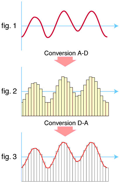 They both work in a similar way: the first tries to approximate the analog signal with a counter. Usually it works in bipolar coordinates with \(3.3V\) standard and output a number according to the formula:
where \(n\) is the number of bits in the ADC. DAC will instead output a signal encoded as unipolar coordinates where, assuming a \(3.3V\) standard, \(1.65V\) represent the zero and the output is given by:
It is possible to pass back and forth between unipolar and bipolar coordinates by negating the first bit.
Evaluation of the Nyquist frequency
This one is a nice one to do.